I have decided to move this blog to another hosting company which offers more features for less cost. Unfortunately, this means the blog URL will change. So in the future new posts will be found at https://riablog.rkeck.me/. What is currently here will remain, although the videos will probably disappear since WordPress.com free hosting does not support video.
The mechanism for the Unlucky Man has been rebuilt with the O-ring pads. This appears to have fixed the ticking problem. It has been running continuously now for several days without getting noisy, so hopefully it will stay quiet. My sister’s end is coming along also, and it is looking great.
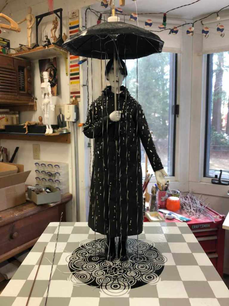
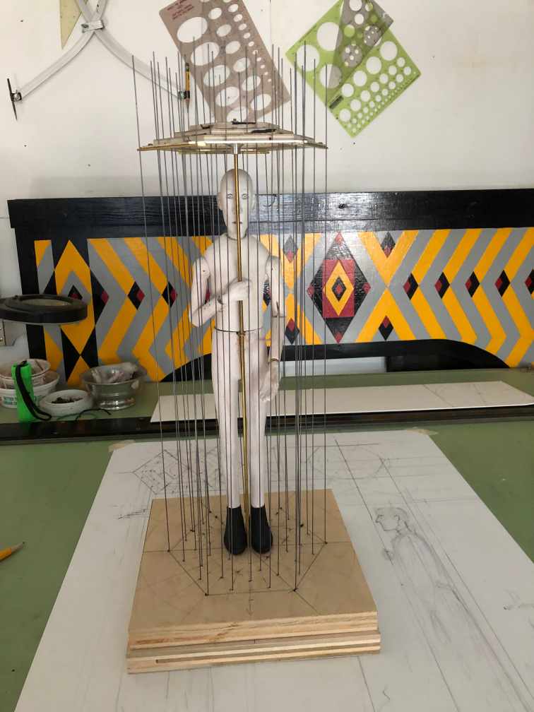
The Unluck Man in progress.
I expect I will ship the mechanism off to my sister tomorrow unless it suddenly re-develops a noise problem.
To eliminate the ticking problem in the mechanism for the Unlucky Man, I decided to try adding O-ring snubbers between the pully shafts and the bearings. Because the O-rings are 1-mm in cross section, I was afraid that if I kept the original 5-mm shaft diameter, the shaft diameter in the O-ring grove of 3-mm might be prone to breaking (resin printed parts are fairly brittle). So I increased the shaft diameter to 6-mm. This necessitated going from bearings that were 4-mm thick to 3-mm thick, which required reprinting the baseplate.
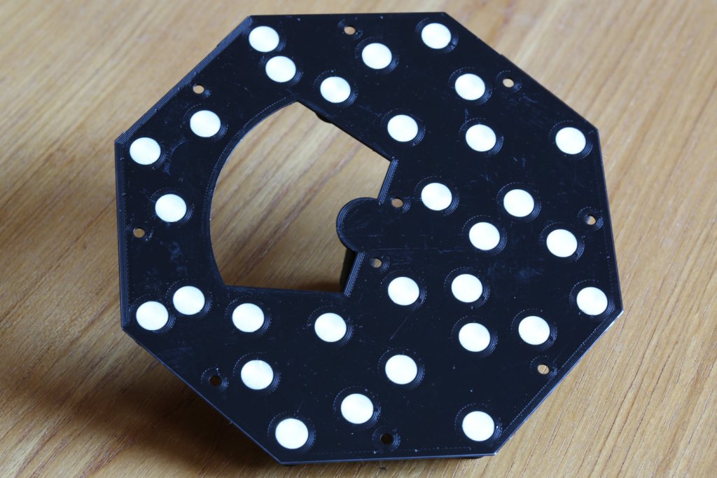
Baseplate bottom view with support plugs still in place.
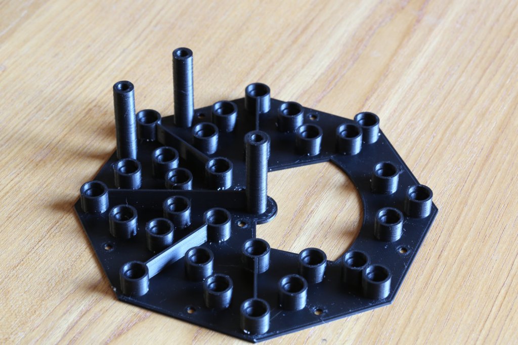
Baseplate top view, with support plugs removed.
Baseplate with bearings installed.
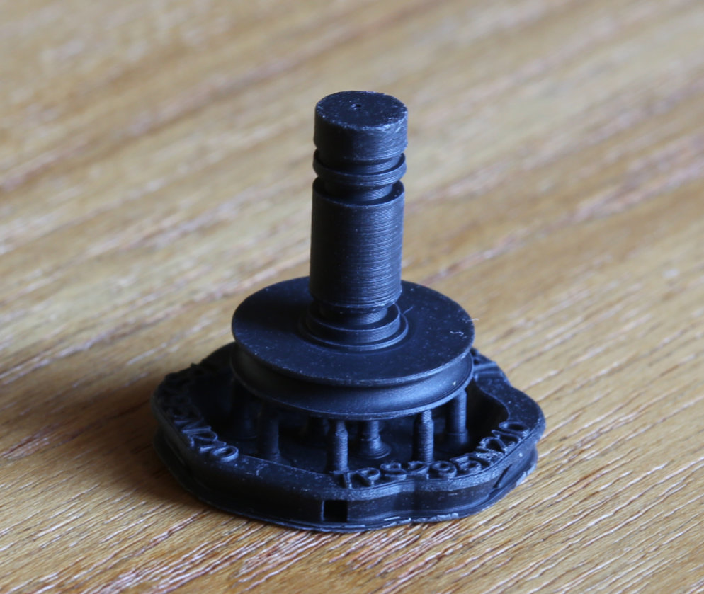
Pulley still on its build support showing the two O-ring grooves and snap ring groove.
In the bottom view you can see the white plugs which support an overhang which supports the bearings. They are printed with a special breakaway plastic and are easily knocked out after printing.
The pully is shown still attached to its support structure. With fused filament printing, a structure like this would not be required; it could print right on the printer baseplate, and it would detach as it cooled. With resin printing, there is no cooling, and parts have to be pried off the printer baseplate. Thus, most parts are printed on a sacrificial base, connected to the part by small posts. The touchpoints to the parts are very small, so these posts are easily broken away. This leaves small defects at the touchpoints, which in this case don’t matter, but otherwise they can be sanded away. Because the top edge of the O-ring and c-clip grooves was unsupported, they are slightly angled, but for this application this was better than dealing with the touchpoint artifacts.
My sister’s latest project is a man standing with an umbrella over his head, with rain pouring on him from the umbrella. Her first idea was to use real water, but I persuaded her this was a bad idea for multiple reasons (clogs, algae, mess, the list goes on). So, she came up with the concept of using wires painted with a black and white spiral. When these rotate, it should look like stuff coming down. There are thirty of these all needing to rotate. The sculpture is only about 12 inches across, so there is not a lot of space. So, I came up with a drive concept that involves using belt driven pulleys.
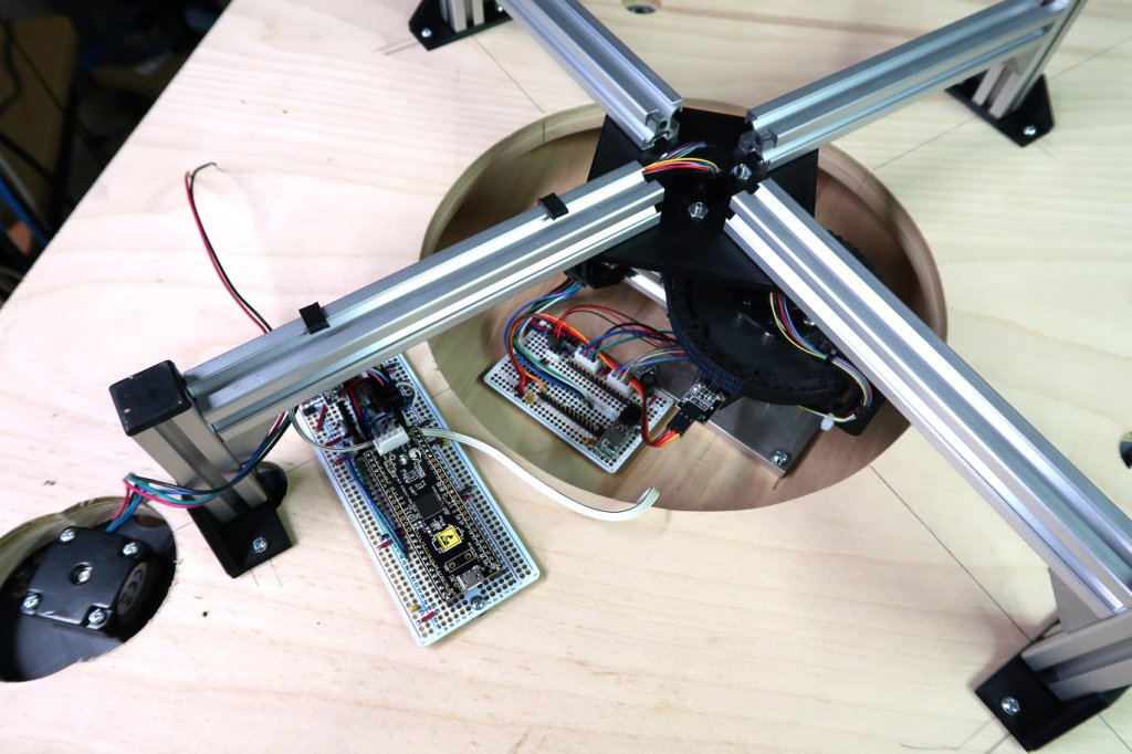
Drive mechanism for the Unlucky Man
The base plate is 3D printed on a fused filament printer and the pulleys, which need remarkable precision, are printed on a resin printer. A pair of miniature ball bearings supports each pulley. The belts are made from NinjaFlex 3D printing filament. It works well for a while, but then it starts ticking. I think for some reason the pulley shafts are loosening up in the bearings and shifting as they revolve causing a tick. I am currently redoing it using O-rings between the pulley shafts and bearings, which will make the pulleys less sensitive to shaft size and provide a damper.
A couple weeks back, I delivered what is now known as “Man Stirring Something Up” or MSSU to my sister. This largely completes my part of it, although I’m still working on dealing with some issues with the sonar distance detector, which it appears can be fixed using a more expensive version of what I started with. Anyhow, the video below shows it assembled with the hoops, operating in my sister’s studio. The sonar detector is being held on with blue masking tape and you will see a laptop off to the side that I was using to debug the sonar detector. My sister is currently in the process of making the surround which will hide the mechanism.
Since much of the code to move everything was written for previous projects, things are moving along rapidly at the moment. There were a few things that need be fixed, primarily where previously written code was never actually used and so there were a few errors. With the addition of the motion of the head, all motion is now functioning as can be seen in the video. Now I need to get the person detector going. While I’ve never used this detector before it looks to be easy to use. Next step after that will be to refine the actual sequence to work as my sister specified. The final step will be the addition of the orbiting LEDs.
I reached a significant milestone with the Spinning Man today. All three parts now can spin at once. It is a relief to know that everything will operate through the spinning slip rings. The video below shows the firmware homing the bowl and the turntable, then it pauses for five seconds, starts the stirring, five second pause, start the bowl, five second pause, start the turntable. After some period, everything is stopped at once.
The video shows the startup homing sequence, then the three motions sequentially starting.
With the completion of the main board for the Stirring Man, the electronics for this project are now largely done. The photo shows the mechanism from the bottom. Once again I’ve used a PSoC5 as the controller and you can see the PSoC prototype board mounted on the main board. The stepper drive board is not yet mounted on the main board. An aluminum “spider” is used to support the sliprings centered over the turntable to feed the wiring from the main board to the turntable.
Bottom view of the Stirring Man. The turntable drive motor is on the lower left. The main control board with PSoC5 board sits beside the turntable cutout. The bottom of the turntable with its electronics board can be seen through the cutout. The aluminum “spider” holds the slipring feeding the wires to the turntable.
With the completion of the mainboard, it’s on to writing code. A good deal of this is already done, since I’ve used the stepper drivers, neo-pixels and the same servo in previous projects, so the low level code can be reused.
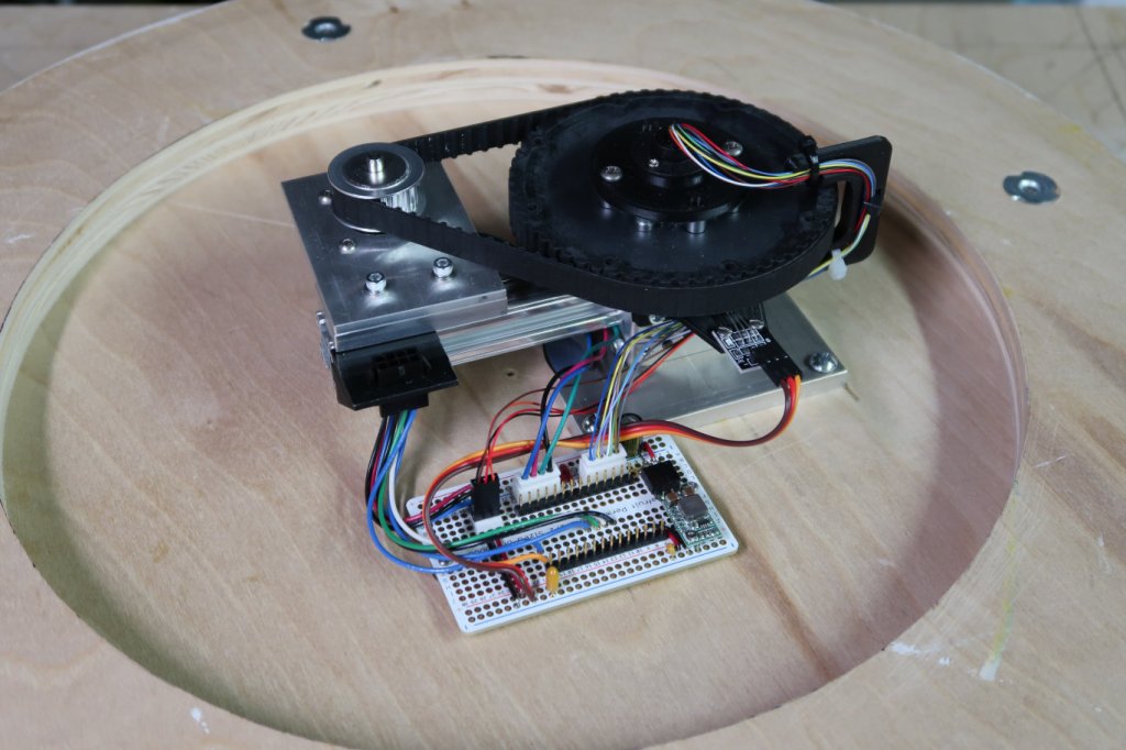
With the completion of the motor drive board for the Stirring Man turntable, the upper 2/3 of the Stirring Man is now complete. With the switch to a stepper drive, I was able to reduce the height of the drive assembly, resulting in a more compact mechanism. The photo shows the completed unit from the bottom.
You can see the wires snaking around the large black pulley and disappearing into the slip ring which transfers them to the bowl on the other side. The stepper drive board will go on the twin rows of headers once some electrical checks are completed.
My sister’s latest project is a figure sitting in a rotating bowl, stirring something in a bowl with the bowl the figure sits in turn orbiting on a platform. And just for good measure, the figure’s head goes up and down and there are orbiting lights around the whole thing. Due to the nested motions implementing this presents a challenge, which is met by things called slip rings, which allow wires to make it through rotating joints. The motions are all relatively low speed, and for this kind of thing you’d normally use gear motors. Unfortunately, gear motors tend to be noisy and that ruins the effect. So I ended up switching to using stepper motors. This involves more wiring, but fortunately small slip rings with 12 wires are available (on Amazon of course) at a reasonable cost.
The video below shows the outer bowl orbiting on its platform. There will be surround around the turntable hiding the mechanism.
The video below shows the man stirring and the bowl rotating. Depending on if they counter-rotate or not, the effective speed of the stirring changes. This video was taken using the gear drive motors so you can get a feel for how noisy they are.
The stepper motors have been retrofitted, but because of the complexity of stepper motor drive, running it with them requires a pretty much fully developed control system due to having to run everything through the slip rings.