I have decided to move this blog to another hosting company which offers more features for less cost. Unfortunately, this means the blog URL will change. So in the future new posts will be found at https://riablog.rkeck.me/. What is currently here will remain, although the videos will probably disappear since WordPress.com free hosting does not support video.
Dealing with electronics, I sometimes order stuff which gets shipped directly from the Philippines, Malaysia or somewhere else on the Pacific rim. Generally they get shipped by air and often arrive in a few days. Recently I ordered something that was shipped from Malaysia. It sat there doing nothing for a week and then suddenly FedEx said it had been delivered. I went and looked at the front door; no package, no footsteps in the freshly fallen snow and furthermore, the delivery time was several hours in the future. Furthermore, when I looked at the tracking detail, it had been put on a truck for delivery in Malaysia and somehow that truck had evidently made it to Rochester, NY USA in a few hours and the package had been delivered. I finally called FedEx and it seems that while it said it had been delivered, it had actually been returned to the sender. Checking the next day, it still said delivered (to Rochester), but the tracking history showed a different story. It has now made it to Taiwan. But the tracking history is kind of amusing and indicates FedEx needs to do a bit of work on its tracking history system.
Looking at this, one could conclude that my package briefly quantum tunneled from Malaysia to Rochester and back. Hopefully it is now on its way to Rochester for real.
My sister picked up the remaining two elevator shafts in early November. Since then she has been busily finishing the whole set of three. I saw them over the Christmas holiday and they are looking great. There are just a few more artistic features she needs to finish. Once it is done, hopefully I’ll be able to get some pictures and a video posted here.
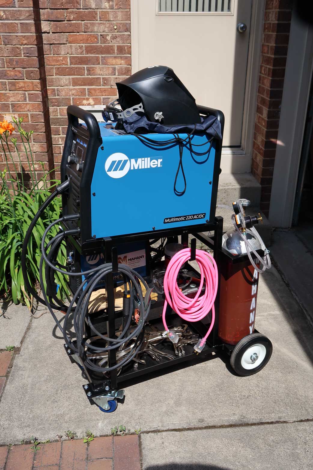
A few weeks ago I delivered the first completed elevator to my sister and picked up two more to automate. With warmer weather arriving, progress on these has been a bit slow. Also, there was a diversion. I had purchased a multi-process welder to replace my MIG welder and I needed to fabricate a new cart for it, since the multi-process welder will accommodate two shielding gas cylinders at once (one for MIG, one for TIG) and most carts only handle only one cylinder. Anyhow, the cart is now done, so progress on the two remaining elevators should get a little quicker.
The MIG welder I gave to my sister, along with a quick welding lesson. She turned out to be a natural welder and was making good looking beads almost immediately. In case you are wondering, there is in fact a welded part in the elevator: the bracket that fastens the belts to the counter-weight was TIG welded together.
The completed two cylinder welding cart, with only one cylinder. Actually, it is not quite complete, since the handle is not done yet. The other benefit over the previous cart is that it will hold my plasma cutter.
The Ghost Elevator continues to come together. Everything but the stuff in the car is working. The video shows it in action. Only the center door has a pointer, but the pointer motor is actually working on all three doors. It is a bit hard to see the figure in the car since the light is not implemented yet.
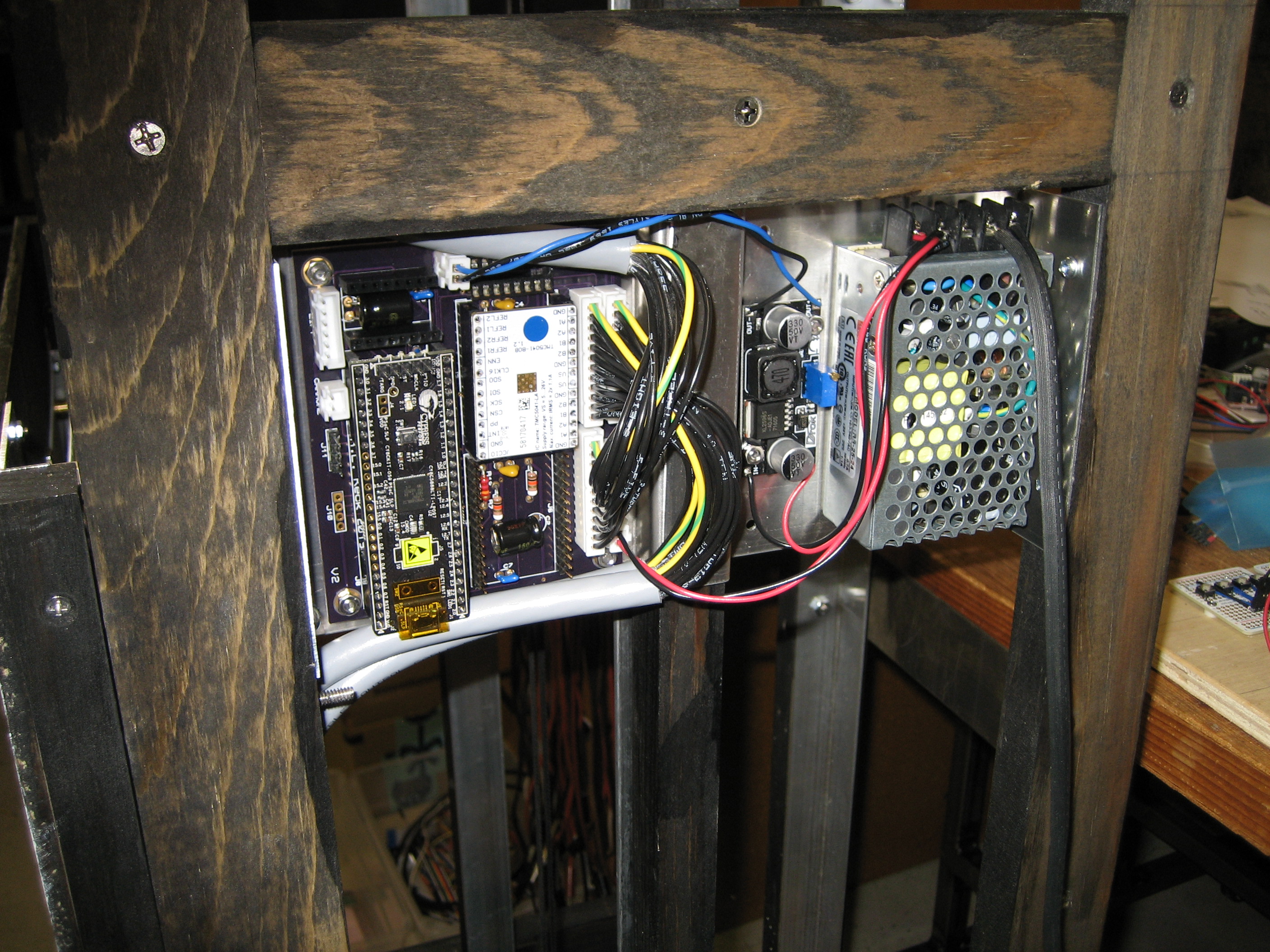
The circuit boards for the elevator electronics came in a few days ago. Actually it was the third set, the first two attempts having fatal errors (don’t ask). The third set had only a minor error easily fixed by adding a wire. The board is now installed in the frame and I am wiring things up, testing and bringing up code. The wiring is somewhat tedious since there are a lot of crimp terminals to install.
The elevator electronics installed in the frame of the shaft. The three 12 wire cables go to the three doors.
At this point, almost everything is working (most of the time) with the exception of the floor indicators, which I’m holding off on until I get everything else working well. There have been a few glitches. One was that it would periodically get a call to the first floor all on its own. This was due to the relatively long cable run to the first floor door resulting in the PWM to the door stepper motor coupling to the call signal. This was fixed with some digital filtering which could be implemented in the PSoC CPLD. I also had a stepper driver board fail and the first one I replaced it with seemed to be DOA. The next one has been working so far, but there may be a QC issue with this board. The other issue is the second floor door is sometimes getting stuck, so the mechanics need to be looked at. Overall, things are going reasonably well so far.
A couple of weeks ago my sister came to visit and brought one of the elevator shafts and cars along with more door assemblies. We spent the weekend retrofitting doors with the new mechanism, but there was not time to get the car operating in the shaft while she was here. My first idea for driving the car worked fine, but I realized it had a potential drawback. The car is being driven with a stepper motor and a “GT2” timing belt. While the belt is operating well below is rated operating tension, if it should break it would be a disaster since neither the car nor the counter weight has a brake. I decided it would be a really good idea to use a double belt system, so if a belt broke, the other would prevent a crash. Between coming up with a double belt system and wiring up doors, it was only today that I got the car operating again.
The video shows the car in action. The doors are not operating yet since I am waiting for the circuit boards for the controller to be fabricated.
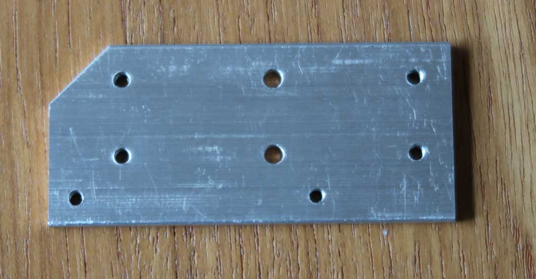
As mentioned in previous posts, the Miniature Elevator needs a lot of precisely located holes and I decided to commission my CNC mill to drill them. I show here a movie of the CNC mill in action drilling elevator door carriage plates. The plates have eight holes each, but there are three size holes and also a spot drill operation so there are three tool changes involved (four if you count the first set up). Ideally, the mill would have an auto tool changer and each plate would be placed on the mill and it would then drill all the the holes changing bits as required. I don’t have that, nor do I even have quick change tooling, so tool changes are a slow operation. So it is faster to set up the mill with one bit at a time and swap all the plates through it, since it is faster to swap a plate than change a bit. So in the movie you will see first the mill doing the spot drilling of eight holes and then you will see four of the holes being drilled. The plate then requires two more passes through the mill to drill two more pairs of holes. In all, with 18 doors and 8 holes per plate, there were 144 holes to drill.
CNC mill spot drilling then drilling four of eight holes in an aluminum carriage plate.
The finished product may not look like much, but remember there are 18 of them and the holes on each one are probably within a couple thousandths of an inch of where they should be.
I decided to upgrade WordPress so I could display videos. So here is a video of one of the doors for the Miniature Elevators in action. This was a quick video I did for my sister. I need to do a better one, but I figured this would do as a test.
As mentioned in a previous post, Holes, my Sherline mill has a digital readout (DRO). Unlike typical DROs which use magnetic or optical sensors, the Sherline works by keeping track of the position of the lead-screws using quadrature detectors mounted in the hand-wheels. While this is not as accurate as real positions sensors, the lead-screws are precise enough that it is generally more than good enough. The readout for the DRO was designed years ago and uses a 2×16 character display which is quite small. The same unit is still being sold today and is quite expensive for what it is.
I decided I wanted an easier to see display and after looking around for something suitable found Nextion displays. These are small graphical LCD displays with an attached microprocessor, touch screen and PC software that allows a GUI to be relatively easily designed and loaded into the Nextion. The Nextion uses a UART interface, so it is easy to run with another micro-controller. Interestingly, I was able to buy a 2.8 inch Nextion for less than I could find a raw 2.8 inch graphical LCD.
It was quite simple to use the Nextion PC software to produce a GUI for my DRO. The result can be seen in the photo below, which shows the Nextion in a 3D printed case next to the original Sherline readout. Since the Nextion includes a touch-screen, no buttons will be required.
The Nextion display (left) in a 3D printed case next to the original Sherline readout.
You can also see at the top of the photo, the Cypress PSoC4 prototyping kit I’m using to develop the DRO firmware. PSoC stands for programmable system on a chip, and the PSoCs are quite amazing devices containing some combination of programmable analog circuitry, various function blocks and effectively a CPLD along with an ARM Cortex CPU. While all of this is not required for this project (the Sherline DRO uses an 80C51 compatible micro) and in the past I might well have done this with a Microchip PIC, the PSoCs have some advantages over typical micro-controllers. One is, the CPLD can be used to synthesize a quadrature decoder, so this operation can be done in hardware rather than software. I plan on using a PSoC5 for the actual display since it has enough CPLD cells to synthesize the required 3 quadrature decoders also has a lot program and data memory. This allows it to easily accommodate FreeRTOS, the use of which I find can considerably simplify program design.
If you were going to mass produce this DRO, the PSoC would be overkill as you can certainly do it using a much cheaper micro-controller. However, for quantity one, the processor cost is not significant. Indeed, the PSoC5 I will use is the KitProg part of the PS0C5 prototyping board and so is effectively free. The PSoC5 prototyping kit contains 2 PS0C5s, one is the prototyping PSoC, the other is used to program the first and is called KitProg. KitProg can be broken off the main board and then reprogrammed to do what you want, albeit with a limited number of pins brought out. I have several KitProgs from the Miniature elevators project available. Even if you need to buy a PSoC5 prototyping kit, at $15 it is hardly expensive (the Nextion was $20) and is insignificant next to the nearly $300 cost of the Sherline electronics.
At this point, I have the quadrature decoders displaying on the Nextion and am working on code to handle input from the touch screen. I also have a custom circuit board in the works to mount the RJ9 connectors used to connect the quadrature encoders to the electronics. The circuit board should be done next week. The custom board was $15 for three, so in the end the DRO will probably cost less than $50 and be considerably nicer than the $300 Sherline.