The CNC Mill

Several years ago I purchased a Little Machine Shop HiTorque Mini Mill, a ball screw kit, steppers and controller, in short, all the stuff need to assemble a CNC milling machine. However, I never got it to the point of actually machining anything until recently. There are several reasons for that. One is that it took some time to figure out the kinks and get issues with the control software resolved. The other is that when I needed to mill something, it was easier just to do it by hand on my Sherline mini mill than do it with CNC. Also, I hadn’t found a CAM processor.

For those unfamiliar with CNC there are several stages to doing it. First, you design the part with a Computer Aided Design (CAD) program. Then the CAD design is processed with a Computer Aided Manufacturing program (CAM) that turns the design into instructions that tell the Computer Numerically Controlled (CNC) machine how to make the part. You can in principle program the machine in a language called G-code directly, but this tends to be error prone and works mostly for simpler parts. After looking at and trying various CAM programs, I finally discovered that Autodesk Fusion 360, which is a cloud based CAD program, also includes a CAM processor. Best of all, it is free for individuals and small companies to use.

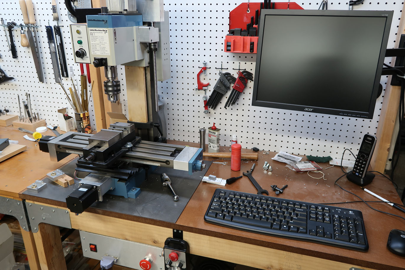
While Fusion is in some ways easier to use than TurboCAD, which I have used for years, I found aspects of it frustrating, in part because it is so different from TurboCAD. So I imported my design into Fusion and then used the CAM processor to generate the G-code to run the machine. After a trial run cutting air, I was able to successfully drill 8 holes in my carriage plate with the CNC mill. I wanted to put a video of this here, but I discovered the free edition of WordPress doesn’t allow this. So until I decide I like this blog thing enough to pay for WordPress all you get is a picture of the CNC mill.

Holes

The carriage plates for the elevator doors (Miniature Elevators) are aluminum flat bar with a bunch of holes in them, eight in fact. The two pairs of these which mount the ball bearings must be precisely located, since there is almost no adjustment. It turns out there is some adjustment because the bearings have 3-mm IDs and are mounted with M3 screws, which are just slightly smaller in diameter than 3-mm. Because there are so many of these plates, 18 in fact, it is useful if all the holes are precisely located so everything just goes together and fits. One of the best ways to do this is to drill the holes on a mill. I have a Sherline miniature mill with digital readout (DRO) on which I made the first few plates, but is surprising how easy it is to screw up a hole location even with the DRO. But I was pleasantly surprised when I made the first plates, that the bearing holes were in the correct location, even though I’d located them based on measuring the v-groove bearing since I did not have manufacturer’s dimensions of the v-groove.

However, it became apparent, based on the screw up rate and the large number of these plates that needed to be made that now would be good time to finally commission the CNC mill I’d put together some time ago, but not actually used yet.

Miniature elevators

From time to time, I work with my sister, Pat Keck (http://patkeck.com) on animating one of her sculptures. The current project is a Ghost Elevator, which actually contains three approximately 1/10 scale three floor elevators. This means there are 9 miniature sliding elevator doors and a lot of small fussy parts. My sister came up with a door mechanism based on that used in the real deal. Fundamentally it was fine, but she used little hand made Delrin wheels for the door slides riding on brass bar, which proved not to reliably glide and also contained an awful lot of fussy assembly. So I redesigned the glides to use miniature v-groove ball bearings riding on ground drill rod. Since there is very limited space to make things fit, I measured my sister’s door mechanism and put the whole thing into a CAD program (I use TurboCAD). This allowed me to try various options without having to build things. The CAD rendering of the door assembly is below.

CAD rendering of elevator door.

More on this to come.